3 Pin Map Sensor Wiring Diagram
3 Pin Map Sensor Wiring Diagram - Unveiling the secrets of 3 & 4 pin map sensor wiring | expert tips for proper wiring techniques!in this comprehensive video, we'll del. Our comprehensive wiring diagram will guide you through the process for 3, 4, and 5 wire sensors. Turn on the ignition key while the engine is off. The wires are connected in the following manor: Let's start by taking a look at how the bosch map sensor pinout works. Web wiring a 3 pin map sensor.
Connect one wire to the map sensor’s power terminal and attach it to a 5v power source. Web i bought a 4th gen map sensor with pig tail. Pin 3 was varying quite a bit. Also in plumbing an fittings and hose. The stress dimension is utilized to compute the amount of air flow right into the engine.
Turn on the ignition key while the engine is off. Web pin 2 measures a steady 2.25v and pin 4 a steady 1.83v, both with the engine idling and off. Web holley efi systems work with either a one wire or two wire knock sensor. Web learn how to install a 3 bar map sensor and get rid of the restrictive map limitations of your stock sensor by upgrading to a 3 bar map sensor. The wires are connected in the following manor:
map sensor wiring PLZ HELP! VW Vortex Volkswagen Forum

Web holley efi systems work with either a one wire or two wire knock sensor. Pin 3 was varying quite a bit. A universal harness comes with a 3 pin metripak connector. Bosch # 0261 230 262. Connect to a suitable ground point on the vehicle’s chassis.
9+ camshaft position sensor wiring diagram LymanBriana

Web by understanding the principles behind the map sensor pinout, you can take better care of your vehicle and ensure it performs at its peak for as long as possible. The wire colors are different and i do not have any wiring diagram with me. Our comprehensive wiring diagram will guide you through the process for 3, 4, and 5.
Map Sensor Wiring Diagram Engine Wiring Work

As per the wiring diagram above, you can: Connect to the signal input pin on the ecu. Web the black wire is the output (load) wire of the sensor. Web i'm just installing alky meth kit to go with my whipple and was wondering where others have spliced into their 3 bar map sensor wiring and what is the wire.
Obd1 Map Sensor Wiring Diagram Wiring Diagram
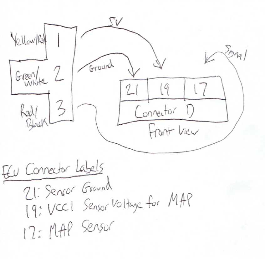
Hp tuner info map sensor slope : Web a map sensing unit or manifold absolute pressure sensor is a device that determines the stress inside the intake manifold of an interior burning engine. Web wiring a 3 pin map sensor. Connect to the signal input pin on the ecu. To connect the 3 wire map sensor, follow the wiring diagram.
Dodge Map Sensor Wiring

Web compatible connector part number: Web i'm thinking the easiest way is to check a corvette with an ls3 and give me the wire colors and which pins they go to. Web i bought a 4th gen map sensor with pig tail. A universal harness comes with a 3 pin metripak connector. Our comprehensive wiring diagram will guide you through.
Zibbix Manifold Absolute Pressure (MAP) Sensor for 19992003 7.3L

Connect to a suitable ground point on the vehicle’s chassis. Between 1v and 4.5v if i recall. Just make sure the correct sensor part number is selected for the correct transistor circuit. Wire pin a to sensor return/ground at the ecu. A universal harness comes with a 3 pin metripak connector.
99 Frc stock map sensor wiring help needed CorvetteForum Chevrolet

Web i'm just installing alky meth kit to go with my whipple and was wondering where others have spliced into their 3 bar map sensor wiring and what is the wire color. Hp tuner info map sensor slope : Connect to a suitable ground point on the vehicle’s chassis. Web pin 2 measures a steady 2.25v and pin 4 a.
Ls1 Maf Wiring Schematic Wiring Diagram

To connect the 3 wire map sensor, follow the wiring diagram below: Web the map sensor is wired to the dme via 3 wires. A universal harness comes with a 3 pin metripak connector. On 2nd key cycle , check engine light. Then connect the red lead to the map sensor’s electrical connector with three wires in the center.
Map Sensor Wiring Diagram

Connect one wire to the map sensor’s power terminal and attach it to a 5v power source. Connect the multimeter’s black lead to a good ground or bind it to the map sensor. Web compatible connector part number: Wiring a 3 pin map sensor requires three wires: The other three pins are then labeled “b”, “c”, and “d”, and are.
Wiring Diagram Toyota Avanza Wiring Flow Schema

Web in general, to test a map sensor with a multimeter: Web by understanding the principles behind the map sensor pinout, you can take better care of your vehicle and ensure it performs at its peak for as long as possible. Connect to a suitable ground point on the vehicle’s chassis. Hp tuner info map sensor slope : The stress.
3 Pin Map Sensor Wiring Diagram - Web in general, to test a map sensor with a multimeter: Then connect the red lead to the map sensor’s electrical connector with three wires in the center. Web the black wire is the output (load) wire of the sensor. I was considering where it runs in the loom along. Wiring a 3 pin map sensor requires three wires: Web the main pin is usually labeled “a” and is responsible for supplying the ecu with voltage for the map sensor. Also in plumbing an fittings and hose. The other three pins are then labeled “b”, “c”, and “d”, and are responsible for providing the ecu with. Web the map sensor is wired to the dme via 3 wires. Web learn how to install a 3 bar map sensor and get rid of the restrictive map limitations of your stock sensor by upgrading to a 3 bar map sensor.
I was considering where it runs in the loom along. Web i'm thinking the easiest way is to check a corvette with an ls3 and give me the wire colors and which pins they go to. Web a map sensing unit or manifold absolute pressure sensor is a device that determines the stress inside the intake manifold of an interior burning engine. Locate the 3 pin map sensor on your engine. Wire pin b, the sensor output, to the ecu’s map sensor input.
Web compatible connector part number: Just make sure the correct sensor part number is selected for the correct transistor circuit. The wire colors are different and i do not have any wiring diagram with me. Unveiling the secrets of 3 & 4 pin map sensor wiring | expert tips for proper wiring techniques!in this comprehensive video, we'll del.
Web wiring a 3 pin map sensor. Web pin 2 measures a steady 2.25v and pin 4 a steady 1.83v, both with the engine idling and off. The stress dimension is utilized to compute the amount of air flow right into the engine.
Bosch # 0261 230 262. It’s pretty straightforward to use this with any of our aftermarket ems options. Web mastering map sensors:
Web Mastering Map Sensors:
The stress dimension is utilized to compute the amount of air flow right into the engine. It’s pretty straightforward to use this with any of our aftermarket ems options. To connect the 3 wire map sensor, follow the wiring diagram below: Web in general, to test a map sensor with a multimeter:
Web I'm Thinking The Easiest Way Is To Check A Corvette With An Ls3 And Give Me The Wire Colors And Which Pins They Go To.
Connect to a suitable ground point on the vehicle’s chassis. Web gm 3 bar map sensor wiring pinout. Web pin 2 measures a steady 2.25v and pin 4 a steady 1.83v, both with the engine idling and off. The wires are connected in the following manor:
Wire Pin A To Sensor Return/Ground At The Ecu.
Web i'm just installing alky meth kit to go with my whipple and was wondering where others have spliced into their 3 bar map sensor wiring and what is the wire color. Just make sure the correct sensor part number is selected for the correct transistor circuit. Then connect the red lead to the map sensor’s electrical connector with three wires in the center. The map sensor wiring diagram is essential for understanding the relationship between air pressure and a vehicle's engine.
Let's Start By Taking A Look At How The Bosch Map Sensor Pinout Works.
A universal harness comes with a 3 pin metripak connector. Replaced fuel rail pressure sensor and an updated pigtail was wired in. Also in plumbing an fittings and hose. Web the black wire is the output (load) wire of the sensor.