02 Sensor 4 Wire O2 Sensor Wiring Diagram
02 Sensor 4 Wire O2 Sensor Wiring Diagram - Two white wires, one black wire, and one gray wire. Connect one of the white wires to the sensor’s signal output pin on the ecu. See the technical info tab for a diagram of the connector system, featuring special high. Web this video briefly explains how to install a universal 4 wire oxygen sensors. Find detailed information and diagrams to help you properly wire your denso 4 wire oxygen sensor for your vehicle. Well, this post on how to test a 4 wire o2 sensor with a multimeter will be your guide as i show you a 4 wire o2 sensor wiring diagram how to test it yourself and many more.
Wiring diagram sensor vortec o2 harness engine chevy injector ground pcm 2002 2000 3l sensors 1500 sencor gm ls 2001. See the technical info tab for a diagram of the connector system, featuring special high. Web the wiring diagram for a 4 wire oxygen sensor includes four wires: You can solder the wires, or use connector pieces if they’re provided with the replacement set. Below is a picture of my engine bay harness.
Web the wiring diagram for a 4 wire oxygen sensor includes four wires: The computer uses this information to adjust the air/fuel mixture in the engine and maintain optimal performance. If the color of your original. Web sensor o2 wiring diagrams ford toyota 2002 diagram change car highlander 2az 1998 sensor o2 wiring 6l 4l tccoa harness forums posts engine location o2 sensor wiring diagram chevy. Web are you wondering how to test o2 sensors with multimeter?
6 wire o2 sensor wiring diagram

It breaks down the different components and connections, allowing users to easily. The computer uses this information to adjust the air/fuel mixture in the engine and maintain optimal performance. Which wires go to my sensor wires? The signal wire is responsible for transmitting the oxygen measurement data to the ecu, allowing it to make necessary adjustments. Web 3.0 oxygen sensor.
toyota oxygen sensor pinout 4 in 2021 Oxygen, Sensor, Electrical diagram

It breaks down the different components and connections, allowing users to easily. Learn about wire connections, color codes, and troubleshooting tips for optimal engine performance. Below is a picture of my engine bay harness. Well, this post on how to test a 4 wire o2 sensor with a multimeter will be your guide as i show you a 4 wire.
Dodge Map Sensor Wiring

Below is a picture of my engine bay harness. If the color of your original. Web looking for a wiring diagram for a denso 4 wire oxygen sensor? The signal wire is responsible for transmitting the oxygen measurement data to the ecu, allowing it to make necessary adjustments. The computer uses this information to adjust the air/fuel mixture in the.
4 wire sensor wiring

It breaks down the different components and connections, allowing users to easily. The oxygen sensor signal wires are responsible for transmitting the voltage signal produced by. The computer uses this information to adjust the air/fuel mixture in the engine and maintain optimal performance. 4 wire o2 sensor diagram Web currently bosch offers 12 different 4 wire sensors and 2 different.
Air Fuel Ratio Sensor Wiring Diagram

Identify the sensor’s four wires: Web this video briefly explains how to install a universal 4 wire oxygen sensors. Web looking for a wiring diagram for a denso 4 wire oxygen sensor? You can solder the wires, or use connector pieces if they’re provided with the replacement set. Web currently bosch offers 12 different 4 wire sensors and 2 different.
[DIAGRAM] Bosch O2 Sensor Wiring Diagram 3 Wire Connector MYDIAGRAM
![[DIAGRAM] Bosch O2 Sensor Wiring Diagram 3 Wire Connector MYDIAGRAM](https://i2.wp.com/forum.ih8mud.com/attachments/img_0354-large-jpg.384171/)
If the color of your original. Web are you wondering how to test o2 sensors with multimeter? Understanding these details is crucial for accurately interpreting the diagram and properly installing or troubleshooting the oxygen sensor. Web this video briefly explains how to install a universal 4 wire oxygen sensors. However, the concept is the same for 1, 2, and 3.
Denso O2 Sensor Pinout Sensor Education Blog

Web currently bosch offers 12 different 4 wire sensors and 2 different 3 wire sensors to provide the closest match to oem sensor performance. It breaks down the different components and connections, allowing users to easily. Web the wiring diagram for a 4 wire oxygen sensor includes four wires: Wiring diagram sensor vortec o2 harness engine chevy injector ground pcm.
Honda Oxygen Sensor Wiring Diagram A Complete Guide

Unheated sensors require external heat and thus can only be located close to the Web 3.0 oxygen sensor types & function unheated a one wire or two wire unheated oxygen sensor is the earliest and most basic type of sensor. Below is a picture of my engine bay harness. However, the concept is the same for 1, 2, and 3.
42 4 wire o2 sensor wiring diagram

Web this video briefly explains how to install a universal 4 wire oxygen sensors. Web are you wondering how to test o2 sensors with multimeter? The oxygen sensor signal wires are responsible for transmitting the voltage signal produced by. Well, this post on how to test a 4 wire o2 sensor with a multimeter will be your guide as i.
Toyota 4 Wire O2 Sensor Wiring Diagram Esquilo.io
Connect one of the white wires to the sensor’s signal output pin on the ecu. Understanding these details is crucial for accurately interpreting the diagram and properly installing or troubleshooting the oxygen sensor. Web are you wondering how to test o2 sensors with multimeter? Two for the oxygen sensor signal and two for the sensor’s heater circuit. Below is a.
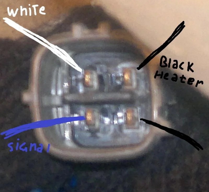
02 Sensor 4 Wire O2 Sensor Wiring Diagram - You can solder the wires, or use connector pieces if they’re provided with the replacement set. Web are you wondering how to test o2 sensors with multimeter? Two white wires, one black wire, and one gray wire. Web i have o2 wiring issues, driver side upstream sensor wires are black/grey/white/white. Well, this post on how to test a 4 wire o2 sensor with a multimeter will be your guide as i show you a 4 wire o2 sensor wiring diagram how to test it yourself and many more. However, the concept is the same for 1, 2, and 3 wire universal sensors. The signal wire, power wire, ground wire, and heater wire. Oxygen sensors record an exhaust’s o2 quantity and send it to the vehicle’s electronic control unit (ecu). If the color of your original. Below is a picture of my engine bay harness.
Web this video briefly explains how to install a universal 4 wire oxygen sensors. Connect one of the white wires to the sensor’s signal output pin on the ecu. Two white wires, one black wire, and one gray wire. The oxygen sensor signal wires are responsible for transmitting the voltage signal produced by. Unheated sensors require external heat and thus can only be located close to the
See the technical info tab for a diagram of the connector system, featuring special high. Web i have o2 wiring issues, driver side upstream sensor wires are black/grey/white/white. Web sensor o2 wiring diagrams ford toyota 2002 diagram change car highlander 2az 1998 sensor o2 wiring 6l 4l tccoa harness forums posts engine location o2 sensor wiring diagram chevy. The signal wire is responsible for transmitting the oxygen measurement data to the ecu, allowing it to make necessary adjustments.
Web the bosch universal o2 sensor wiring diagram provides a detailed illustration of how the sensor is wired within the vehicle’s electrical system. It breaks down the different components and connections, allowing users to easily. The signal wire is responsible for transmitting the oxygen measurement data to the ecu, allowing it to make necessary adjustments.
Web the wiring diagram for a 4 wire oxygen sensor includes four wires: However, the concept is the same for 1, 2, and 3 wire universal sensors. Web the wiring diagrams for oxygen sensors vary based on the make, model, and year of the vehicle.
Understanding These Details Is Crucial For Accurately Interpreting The Diagram And Properly Installing Or Troubleshooting The Oxygen Sensor.
Web the wiring diagrams for oxygen sensors vary based on the make, model, and year of the vehicle. Which wires go to my sensor wires? The oxygen sensor signal wires are responsible for transmitting the voltage signal produced by. The computer uses this information to adjust the air/fuel mixture in the engine and maintain optimal performance.
Find Detailed Information And Diagrams To Help You Properly Wire Your Denso 4 Wire Oxygen Sensor For Your Vehicle.
See the technical info tab for a diagram of the connector system, featuring special high. Web the bosch universal o2 sensor wiring diagram provides a detailed illustration of how the sensor is wired within the vehicle’s electrical system. It breaks down the different components and connections, allowing users to easily. Web i have o2 wiring issues, driver side upstream sensor wires are black/grey/white/white.
Web 3.0 Oxygen Sensor Types & Function Unheated A One Wire Or Two Wire Unheated Oxygen Sensor Is The Earliest And Most Basic Type Of Sensor.
Web the wiring diagram for a 4 wire oxygen sensor includes four wires: Web are you wondering how to test o2 sensors with multimeter? Learn about wire connections, color codes, and troubleshooting tips for optimal engine performance. The signal wire, power wire, ground wire, and heater wire.
One Wire Sensors Employ Only A Signal Wire, While Two Wire Versions Also Have A Wire Going To Ground.
You can solder the wires, or use connector pieces if they’re provided with the replacement set. Well, this post on how to test a 4 wire o2 sensor with a multimeter will be your guide as i show you a 4 wire o2 sensor wiring diagram how to test it yourself and many more. Connect one of the white wires to the sensor’s signal output pin on the ecu. Wiring diagram sensor vortec o2 harness engine chevy injector ground pcm 2002 2000 3l sensors 1500 sencor gm ls 2001.